Minor head losses in pipes
When velocity of flowing liquid changes (either in magnitude or in direction) then there is minor losses in head (Energy) which is called minor head losses in pipes. In case of long pipes these losses are usually quite small as compared with the loss of energy due to friction and hence these are termed as 'Minor head losses' which may even be neglected without serious error, however, in short pipes these losses may sometimes outweigh the friction loss. In addition, minor head losses are negligible when they include only 5% or less of the friction head loss, So, it can be concluded that minor head losses are significant for short pipes only.
Ad:
Types of minor head losses
There are different causes of minor head losses; some of them
are discussed below.
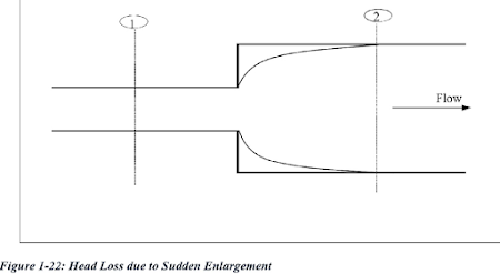
i)Head losses due to sudden expansion of pipe:
 |
| Fig: Head losses due to certain enlargement |
Let, Px= pressure developed inside the pipe due to liquid eddies on area (A2-A1)
he = loss of head due to sudden enlargement.
Now, by using Bernoulli's equation between section 1 and 2
ii)Loss of head due to sudden Shrinkage:
Consider a section 1 and 2 in a pipe where liquid is flowing and there is sudden contraction in the area between section 1 and 2 as shown in fig below. As the liquid flows from larger pipe to smaller pipe, the area of flow goes on decreasing and becomes minimum at a section C', called vena-contracta. After section C', a sudden enlargement of the area takes place.
The loss of head due to sudden contraction is actually due to sudden enlargement from vena-contracta (i.e. section C) to smaller pipe (i.e. section 2)
Let Ac and Vc be the area and velocity of flow at section
'C'. Let A2 and V2 be the area and velocity of flow at section 2.
'he' is actually loss of head due to sudden enlargement from section 'C' to 2 which is given by
From the continuity equation
A1V1=AcVc=A2V2
 |
| Fig: Head losses due to certain contraction |
iii)Loss of head while entering a pipe:
When a liquid enters a pipe from a large vessel (or tank),
some loss of energy occurs at the entrance to the pipe which is known as inlet
loss of energy. The loss is similar to that in the case of a sudden contraction,
Now, Entrance loss (hi) is
Where 'V' is the
velocity of liquid in pipe and 'Ki' is the coefficient of entrance. The loss of
energy actually depends on the form of the entrance. If not given, take 'hi'= 0.5.
Ad:
Value of 'Ki' with different entrance shapes
|
Type of entrance |
|
|
Sharp cornered |
0.5 (common case) |
|
Rounded |
0.2 |
|
Bell mouthed |
0.05 |
iv)Loss of head at the departure (exit) of pipe:
This is the loss of head due to the velocity of liquid at
outlet of pipe which is dissipated either in the form of a free jet (if outlet
of the pipe is free) or it is lost in the tank or reservoir (if outlet of the
pipe is connected to the tank or reservoir).
Now, Exit loss (ho) is
where, 'V' is the Velocity at outlet of pipe and 'Ko' is the coefficient of exit. If not given, take 'Ko' =1
v)Loss of head due to bend in pipe:
When there is any bend in a pipe, the velocity of flow changes, due to the separation of flow from the boundary and also formation of eddies take place. Thus, the energy is lost.
Now Loss of head due to bend 'hb' is
Where, 'V' is the Velocity of flow and 'Kb' is the
Coefficient of bend,
Table: Value of 'Kb' with
different bend condition
|
Bend |
|
|
Sharp 900 |
1.2 |
|
Sharp 1800 |
2.2 |
vi)Loss of head in various pipes fittings:
Here, Loss of head in various pipe fittings such as valves, couplings
(hi) is
Where, 'V' is the Velocity of flow and 'K' is the Coefficient of pipe-
fitting.
Table: Value of 'Kp' with Pipefitting
|
Pipe Fitting |
|
|
Standard T (branch flow) |
1.8 |
|
Standard T (line flow) |
0.4 |
|
elbow (long radius) |
0.6 |
|
900 elbow (short radius) |
1.5 |
|
Gate valve (fully open) |
0.2 |
vii)Loss of energy due to obstruction in pipe:
While there is present obstruction in pipe, the loss of energy takes place due to the reduction of x-sectional area of pipe. This loss will take place due to sudden enlargement of flow area beyond the obstruction.
Now, the obstruction loss (![]() ) is
) is
Where, 'V' is the velocity of flow, 'A' is the x-sectional area of pipe,
'a' is the maximum area of obstruction, 'Vc' is the velocity at vena-contracta
Equivalent length of pipe for representing minor head losses inside the pipe:
Equivalent Frictional head loss due to minor loss
Now, equivalent length of pipe representing minor head loss (Le) is
For more than one type of minor head losses, Coefficient 'K'
represents the sum of several losses.
So, total head loss (hT) is
Read more:


Comments
Post a Comment